
Some equipment needs to read the battery, not simply draw power from it. A custom smart battery pack combines cells, a battery management system, sensing and a communication interface to exchange operating data with the host machine. Depending on the project, it can report voltage, current, temperature, state of charge, alarms, protection status and charging permission.
We develop project-specific Li-ion and LiFePO4 battery packs with CAN, RS485, UART, SMBus, I2C, Bluetooth or other approved interfaces. Voltage, current, BMS architecture, connector, message definitions and enclosure are matched to the equipment rather than a generic feature list.
The battery may be able to power the load but still fail integration if the host expects different message IDs, scaling, byte order, timing, alarm behavior or wake-up logic. Communication requirements should be agreed before prototype hardware and firmware are frozen.
What Makes a Battery Pack “Smart”?
A basic battery management system protects the cells against operating conditions such as excessive voltage, excessive current and unsafe temperature. A smart BMS adds measurement, calculation, event handling and communication functions that allow the equipment controller, charger or service tool to understand battery status.
- Electrical measurements: Pack voltage, cell-group voltages, charge and discharge current, and available power limits where required.
- Temperature data: Cell, BMS, connector or enclosure temperatures from project-specific sensor locations.
- Calculated values: State of charge, remaining capacity, cycle count and state of health when supported by the selected BMS.
- Protection status: Overvoltage, undervoltage, overcurrent, short-circuit and temperature warnings or shutdown states.
- System control: Charge and discharge permission, contactor control, precharge status, sleep, wake and power-limit messages.
- Service information: Firmware version, serial number, event history and diagnostic data where the project requires traceability.
Best-Fit Applications
A custom smart battery pack is useful when the equipment must monitor energy availability, coordinate charging, control power or record battery condition. Typical applications include:
- AGVs, AMRs, service robots, inspection robots and mobile automation platforms
- Industrial machines, instruments and electrically powered work equipment
- Stationary energy storage, telecom backup and modular power systems
- Electric vehicles, off-road vehicles and special mobile equipment
- High-power UPS, mobile power stations and intelligent backup modules
- Medical, laboratory and professional equipment requiring battery identification or fuel-gauge data
- OEM products using automatic docking, fleet charging or remote diagnostics
Basic BMS vs. Smart Battery Management System
| Design area | Basic protection BMS | Smart BMS |
|---|---|---|
| Primary purpose | Protect cells by interrupting charge or discharge under defined fault conditions | Protect cells and exchange battery measurements, limits, status and diagnostics with other controllers |
| Typical interface | No external data interface, or a simple service connection | CAN, RS485, UART, SMBus, I2C, Bluetooth or a project-specific interface |
| State of charge | May not be available externally | Can report calculated SOC and remaining capacity after project-specific configuration |
| System coordination | Usually relies on fixed protection thresholds | Can provide charge/discharge limits, warnings, permissions and controlled shutdown states |
| Development effort | Lower when the application only needs correct electrical protection | Requires protocol definition, firmware configuration, integration testing and revision control |
A smart BMS is not necessary for every battery. Communication is justified when the host needs reliable battery data, coordinated charging, controlled power reduction, fleet diagnostics or service records.
CAN, RS485, UART, SMBus, I2C or Bluetooth?
The interface should be selected around the host controller, electrical environment, network and software requirements. CAN and RS485 are common in industrial projects, but they are not interchangeable.
| Interface | Typical smart-battery use | Information that must be agreed |
|---|---|---|
| CAN / CAN bus | Robotics, vehicles, mobile machines, energy storage and controllers with multiple network nodes | Bit rate, standard or extended identifiers, signal map or DBC, cycle time, timeout, termination and fault behavior |
| RS485 | Industrial equipment, chargers, storage systems and service tools needing a robust serial physical interface | Two-wire or four-wire arrangement, baud rate, parity, address, termination, register map and the application protocol |
| UART | Short internal point-to-point links, development access or a service connection | Logic level, baud rate, frame format, connector, isolation and command structure |
| SMBus | Portable equipment and smart batteries using an established host, charger and fuel-gauge architecture | Supported commands, battery identification, authentication needs, host behavior and connector pinout |
| I2C | Short-distance board-level communication inside compact equipment | Voltage level, device address, bus loading, pull-ups, cable length and register definition |
| Bluetooth | Commissioning, maintenance, mobile display or local service access | App ownership, data permissions, pairing, parameter access and whether wireless control is allowed |
RS485 defines electrical signaling, not the meaning of the data. Modbus RTU is one possible protocol over RS485, while many BMS products use proprietary frames. An “RS485 BMS” request should include the register map or message document.

Define the BMS Communication Protocol Before Sampling
The protocol document should define what is transmitted, how values are encoded and what the host must do when data is missing or indicates a fault.
- Network settings: CAN bit rate or serial baud rate, node addresses, bus termination and isolation requirement.
- Message definition: CAN IDs, registers or commands, read/write permissions and supported operating modes.
- Signal encoding: Units, scaling, offset, byte order, signed or unsigned format and invalid-value definition.
- Transmission timing: Cyclic rate, event-driven messages, request/response timing and startup sequence.
- Timeout behavior: Time before a missing message becomes a warning, derating condition or controlled shutdown.
- Alarm logic: Warning, protection and recovery states for voltage, current, temperature, communication and sensor faults.
- Version control: Protocol revision, BMS firmware, parameter file and approved host-software version.
To match an existing protocol, provide the DBC file, register table or complete frame description. A communication log is also useful for deciding whether configuration is sufficient or firmware changes and joint controller testing are required.
SOC, Remaining Capacity and State of Health
Battery state of charge is an estimate rather than a directly measured quantity. A fuel-gauge algorithm may combine current integration, open-circuit-voltage behavior, temperature compensation and a cell model. Accuracy depends on cell data, current sensing and calibration.
SOC should be validated over representative full and partial cycles. Temperature, high current and aging can change accuracy, and the host needs a defined response when reported SOC and pack-voltage limits do not agree.
State of health may refer to remaining capacity, internal resistance, power capability or a combination. Its definition and acceptance threshold should be documented for consistent fleet maintenance.
Protection Parameters and Host-System Response
A lithium battery BMS must use protection values that match the selected cells, series-parallel configuration, current path, temperature sensors and application limits. Configurable software does not make every threshold safe. Cell datasheets, validated test data and the equipment load profile establish the allowable window.
- Cell and pack overvoltage and undervoltage thresholds, delays and recovery conditions
- Charge and discharge overcurrent levels, peak-current duration and short-circuit response
- High- and low-temperature charge and discharge limits at the selected sensor positions
- Cell-balancing start conditions, balance current and operating state
- Warnings and derating limits that occur before a protective shutdown where appropriate
- Contactor, MOSFET, precharge and charger-control logic for the selected voltage architecture
The host should distinguish a warning from immediate protection. A robot may reduce speed when power is limited, complete a controlled stop at low SOC and disconnect rapidly only for a severe fault. These responses must be agreed with the machine-control team.
Charger, Docking Station and BMS Integration
A smart battery and charger may exchange voltage limits, current limits, charging permission, temperature status and fault information. This is especially useful for automatic docking, fleet charging and high-power systems. The charger must still match the chemistry, series count and maximum approved voltage even when communication is present.
For docking, review contact sequence, polarity prevention, inrush behavior, charger discovery, wake-up and communication loss during charging. Mechanical tolerance and contact wear also matter.
Low-Voltage and High-Voltage Smart Battery Architecture
The published development range may extend from approximately 12V to 800V or higher, but one BMS architecture does not cover that entire range. A compact low-voltage battery can often use one board with MOSFET switching. A custom high-voltage battery system may instead use distributed cell-monitoring units, a master controller, contactors, precharge, a high-voltage interlock and an isolation-monitoring interface.
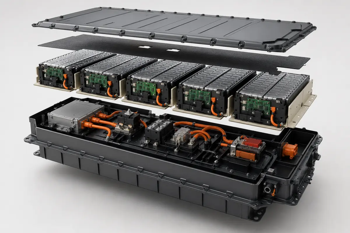
High-voltage communication also coordinates power-up, pack checks, precharge and main contactors. Fault handling, contactor feedback and restart permissions should be tested as complete sequences.
LiFePO4 or Li-Ion for a Smart Battery Pack?
Smart communication can be applied to both LiFePO4 and other Li-ion chemistries such as NMC. Chemistry should be selected from the energy, power, cycle-life, temperature, packaging and safety requirements—not from the communication method.
| Chemistry direction | Common project priority | Smart-BMS considerations |
|---|---|---|
| LiFePO4 | Frequent cycling, stable industrial use and applications where long service life is important | Use the correct LiFePO4 voltage model, SOC calibration and charge-temperature limits; do not apply an NMC parameter set |
| NMC / conventional Li-ion | Higher energy density, lower pack mass or more compact packaging | Match the exact cell voltage, current and temperature limits and validate SOC over the intended load profile |
Cylindrical, prismatic or pouch cells can be used where appropriate. The chosen cell must provide the required continuous current, pulse current, usable energy and temperature performance. A sophisticated battery management system cannot correct an unsuitable cell or an undersized series-parallel configuration.
Connector, Wiring, EMC and Service Access
Power and communication interfaces should be designed together. Drawings should identify power pins, communication pairs, wake lines, shielding, grounding and service connections. Keying, locks and strain relief help reduce assembly and vibration risk.
- Separate sensitive signal wiring from high-current conductors where the layout allows.
- Define CAN or RS485 termination at system level so the battery does not duplicate or omit the required termination.
- Review cable shielding and reference-ground strategy with the equipment-control team.
- Confirm connector current, voltage, environmental rating, mating life and touch protection.
- Provide safe access for firmware loading, diagnostics or parameter confirmation when service is required.
BMS layout, harness routing, inverter noise, charger behavior and grounding can affect EMC and communication. Define required EMC tests and operating modes before finalizing the enclosure and harness.
Custom Smart Battery Specification Range
| Specification | Project-specific options | How it is confirmed |
|---|---|---|
| Voltage | Approximately 12V to 800V+ according to the equipment voltage window | Cell count, maximum charge voltage, minimum load voltage and architecture review |
| Capacity and energy | Defined from runtime, load profile, usable SOC window, space and weight | Calculation followed by prototype charge-discharge testing |
| Chemistry | LiFePO4 or Li-ion/NMC using cylindrical, prismatic or pouch formats where suitable | Cell-data review, supplier approval and application validation |
| Communication | CAN, RS485, UART, SMBus, I2C, Bluetooth or approved custom interface | Protocol document, electrical interface check and host-integration test |
| Reported data | Voltage, current, temperature, SOC, SOH, cycles, alarms, limits and status | Signal list, scaling, accuracy target and test procedure |
| Protection | Voltage, current, short-circuit, temperature and system-specific logic | Cell limits, BMS configuration and fault-injection validation |
| Housing | Shrink wrap, plastic case, metal enclosure or project-specific sealed structure | Mechanical drawing, fit review and applicable environmental testing |
| Documentation | Approved specification, drawings, protocol, labels, test records, UN 38.3 planning and SDS/MSDS | Final configuration, destination, shipping method and applicable product standard |
Prototype and BMS Communication Testing
Test the prototype inside the equipment as well as on the bench, confirming that electrical performance and transmitted data describe the same event.
- Signal verification: Compare transmitted voltage, current and temperature against calibrated reference measurements.
- SOC validation: Run representative full and partial cycles at expected loads and temperatures, then compare indicated and delivered capacity.
- Protocol checks: Verify every required message, register, command, unit, scaling, byte order and update rate.
- Timeout testing: Disconnect or delay communication and confirm the battery, charger and host enter the approved state.
- Protection tests: Confirm warnings, current limits, shutdown conditions and recovery behavior without exceeding the approved test method.
- Charger integration: Test charge permission, voltage/current limits, wake-up and interrupted charging.
- Load testing: Measure voltage sag, connector loss and temperature rise at continuous and peak operating profiles.
- Environmental checks: Add vibration, thermal cycling, ingress or EMC testing when required by the application.
Our battery quality control process can include incoming cell checks, BMS verification, assembly inspection, aging, final electrical testing and communication checks. Acceptance criteria should be agreed before pilot production so the same parameter file and test limits can be applied consistently to later batches.
Firmware, Configuration and Production Traceability
Smart BMS software becomes part of the product specification. Firmware version, calibration values, protection parameters and protocol revision should be controlled with the bill of materials. If a setting changes, the effect on the charger, host controller, test procedure and existing fleet must be reviewed.
Useful records include serial number, cell batch, BMS hardware and firmware, parameter revision, calibration and final communication test. Fleet projects depend on consistent behavior between packs.
Certification and Export Documentation Planning
Compliance depends on the final configuration, application and destination. UN 38.3 addresses lithium-battery transport testing; it is not complete product-safety approval for the machine. IEC 62133-2 may be relevant to portable sealed lithium batteries, while IEC 62619 may apply to certain industrial applications. Confirm the route from the finished product category and market.
CE marking is based on the applicable European legislation for the finished product and the manufacturer’s conformity assessment. It should not be presented as an automatic result of using a particular BMS or completing UN 38.3. CB Scheme support likewise requires an applicable IEC standard and an agreed certification route.
Depending on the approved project, documentation support can include the battery specification, electrical and mechanical drawings, connector pinout, communication protocol, inspection records, labels, SDS/MSDS, UN 38.3 test planning and test summary, and reports required by the agreed validation plan.
Information Needed for a Custom Smart Battery Quote
For an efficient feasibility review and quotation, send as many of the following items as possible:
- Application, equipment type and expected operating sequence
- Nominal voltage, maximum charge voltage, capacity or runtime target
- Continuous current, peak current, peak duration and regenerative current where applicable
- Battery-space drawing, size limit, weight target, mounting and cable direction
- Cell chemistry preference and expected cycle life
- Communication interface, protocol document, DBC file or register map
- Required data signals, units, update rates, alarms and host responses
- Connector model, complete pinout and charger information
- Operating temperature, vibration, ingress and EMC requirements
- Destination market, certification target, sample quantity and annual forecast
Related Custom Battery Support
Review our complete custom battery pack engineering service, see how smart communication is applied in a custom robot battery pack or 48V LiFePO4 battery for AGV and robotics, compare available models in the battery product catalog, or send your protocol and electrical requirements for review.
Frequently Asked Questions
Can you match our existing CAN or RS485 protocol?
Yes, feasibility can be reviewed from the complete protocol document, DBC file or register map. We also need bit or baud rate, connector pinout, required messages, timing and fault behavior. Some projects can use configurable BMS firmware; others require supplier-level software development.
Is RS485 the same as Modbus RTU?
No. RS485 defines an electrical communication interface. Modbus RTU is one application protocol that can operate over RS485. A battery using proprietary RS485 frames will not automatically communicate with a Modbus controller.
Can the smart BMS report accurate state of charge?
It can report calculated SOC, but accuracy depends on the fuel-gauge method, current-sensor calibration, cell model, temperature, load profile and learning conditions. SOC should be validated over representative cycles in the actual application.
Can protection values and alarm thresholds be adjusted?
Many BMS parameters are configurable, but approved values must remain within the limits of the selected cells, conductors, switching components, charger and equipment. Adjustable does not mean unrestricted.
Can one battery communicate with both the machine and charger?
Yes, depending on the BMS architecture and interface availability. The network topology, message ownership, addresses, termination and behavior during charging must be defined before hardware selection.
Does every lithium battery need a smart BMS?
No. Every pack needs protection appropriate to its configuration and application, but a communication interface is only justified when the host, charger or service process needs battery data or coordinated control.
Can Bluetooth be used as the main control connection?
Bluetooth is often useful for commissioning, local display and maintenance. Whether it can perform a control function depends on the risk assessment, connection reliability, access control and equipment requirements. It should not be assumed to replace a wired safety-related interface.
Can a smart battery pack operate from 12V to 800V?
Projects across that broad range can be reviewed, but the architecture changes substantially. Low-voltage packs may use one protection board, while high-voltage systems usually require distributed monitoring, contactors, precharge and additional insulation and service controls.
What documents should I send before sampling?
Send the voltage and load requirements, battery-bay drawing, charger information, connector pinout, protocol document or DBC file, required signals, environmental conditions and certification market. A host communication log and existing-battery information can speed up the review.