
A custom 21700 battery pack is designed around the finished equipment rather than a fixed catalog shell. The cell format can provide more capacity per cell than many 18650 options, but cell size alone does not determine whether the battery will deliver the required runtime, peak current or service life.
A dependable pack requires the selected 21700 lithium-ion cells, series-parallel layout, BMS, interconnects, insulation, temperature sensors, wiring, connector and enclosure to work as one system. Charging voltage, equipment cutoff, load peaks, operating temperature, vibration and production consistency must be reviewed before the design is frozen.
We develop project-specific 21700 rechargeable battery packs for robots, portable instruments, inspection equipment, mobile machines, professional electronics and other OEM products. Voltage, capacity, current capability, shape, communication and documentation are confirmed from the actual application instead of being inferred from a generic “21700 battery” description.
What Is a 21700 Lithium-Ion Battery Pack?
A 21700 cell is a cylindrical rechargeable lithium-ion format with dimensions of approximately 21 mm in diameter and 70 mm in length. The name describes the general format, not a single electrical specification. Exact maximum dimensions, terminal construction, capacity, weight, charge limit and allowable current vary by cell manufacturer and model.
Cells are connected in series to raise voltage and in parallel to raise capacity and available current. The cell assembly is then integrated with a battery management system, electrical insulation, current conductors, temperature sensing, wire harnesses and mechanical protection. A smart pack can also include state-of-charge reporting, event records and communication with the host equipment or charger.

Why Choose 21700 Cells for a Custom Battery Pack?
The main pack-level advantage is not simply that a 21700 cell is larger. A suitable 21700 cell can help reach an energy or power target with fewer cells and fewer parallel connections than a design based on smaller cells. This may simplify the cell matrix, reduce weld count and create more space for insulation, conductors or a BMS.
- Higher capacity per cell: Energy-focused 21700 cells can reduce the number of cells needed for a specified pack capacity.
- Power-cell options: High-current models can support motor, robotics and mobile-equipment loads when used within their approved limits.
- Lower connection count: Fewer cells can mean fewer holders, welds and electrical junctions for some pack architectures.
- Efficient regular layouts: The format works well in rectangular, cylindrical or module-style enclosures that have enough width and height.
- Scalable OEM configurations: Series and parallel counts can be adjusted for different voltage, energy and current requirements.
These benefits are application-dependent. A larger cell can be harder to fit into a narrow or irregular battery compartment, and reducing cell count does not automatically solve thermal, current-sharing or supply-chain requirements. The complete pack should be compared rather than choosing by cell capacity alone.
Best-Fit Applications
A custom 21700 lithium battery pack is a strong candidate when the device needs compact rechargeable energy, meaningful peak-current capability or fewer cells than an equivalent smaller-cell layout. Typical applications include:
- Service robots, inspection robots, UGVs and compact AMR platforms
- Portable instruments, analyzers and field-test equipment
- Professional lighting, mobile imaging and communication devices
- Inspection cameras, pipe-crawling equipment and remote sensors
- Compact industrial machines and motor-driven portable equipment
- Backup modules, mobile power units and embedded OEM energy systems
- Replacement batteries where the enclosure can be redesigned around 21700 cells
The application name is only a starting point. A robot with repeated acceleration requires a different cell, conductor and BMS design from an instrument with a low, steady load. Runtime, current profile, charging method and installation space must be reviewed together.
21700 Battery Voltage and Series Configuration
Many conventional 21700 lithium-ion cells are rated at 3.6V or 3.7V nominal and charge to 4.2V, but the exact cell specification always controls the pack settings. Series count must be selected from the equipment’s complete voltage window rather than a marketing label such as 12V, 24V or 48V.
| Series configuration | Typical nominal voltage | Typical maximum charge voltage | Example equipment class |
|---|---|---|---|
| 2S | 7.2V / 7.4V | 8.4V | Portable electronics and compact instruments |
| 3S | 10.8V / 11.1V | 12.6V | 12V-class portable equipment where the voltage window is compatible |
| 4S | 14.4V / 14.8V | 16.8V | Robotics, lighting and professional electronics |
| 6S | 21.6V / 22.2V | 25.2V | Motor-driven devices and mobile equipment |
| 7S | 25.2V / 25.9V | 29.4V | 24V-class equipment with an approved controller range |
| 10S | 36V / 37V | 42V | Robots and industrial mobile platforms |
| 13S | 46.8V / 48.1V | 54.6V | 48V-class systems with compatible electronics |
| 20S | 72V / 74V | 84V | Higher-voltage mobile and industrial equipment |
| 26S | 93.6V / 96.2V | 109.2V | Approximately 96V nominal systems requiring additional insulation review |
Illustrative values for conventional 4.2V-charge lithium-ion cells. The selected cell datasheet, charger and equipment limits determine the approved settings.
The equipment must tolerate both the fully charged voltage and the declining voltage during discharge. The design team should provide the maximum allowed input, normal operating range, low-voltage shutdown point, charger output and any regenerative or back-feed conditions.
How Series and Parallel Counts Are Calculated
Series count determines voltage. Parallel count determines nominal capacity and shares load current among cells. The final parallel count must also allow for voltage sag, temperature, aging, usable state-of-charge range and the approved current per cell.
Illustrative 10S4P example:
Using a 3.6V, 5.0Ah 21700 cell, ten series groups provide approximately 36V nominal. Four cells in each parallel group provide approximately 20Ah.
The configuration uses 40 cells and has a nominal energy of approximately 720Wh before allowances for load, temperature, conversion losses, cutoff settings and aging.
This calculation explains series and parallel relationships only. It is not a cell-current, BMS, conductor or thermal recommendation.
A 20Ah requirement cannot be approved from capacity alone. If the equipment draws 40A continuously and 80A during acceleration, the cell model, number of parallel paths, interconnect resistance, BMS loss and temperature rise must all support those loads with an appropriate engineering margin.
21700 vs. 18650 Battery Pack
The frequent question “Is 21700 better than 18650?” has no universal answer. The useful comparison is the finished battery pack inside the actual device.
| Design factor | 21700 format | 18650 format |
|---|---|---|
| Cell size | Approximately 21 mm × 70 mm, with exact limits defined by the selected cell | Approximately 18 mm × 65 mm, with exact limits defined by the selected cell |
| Capacity per cell | Often higher, which can reduce cell count for some energy targets | Often lower per cell, so more parallel cells may be required |
| Layout flexibility | Efficient in regular spaces that can accept the larger diameter and length | Smaller cells can fit narrow, stepped or irregular spaces more easily |
| Connection count | May reduce holders, welds and connections for a given pack energy | May need more cells and welds, depending on the selected models |
| Power options | Energy-focused and high-current models are available | Many established energy and power models are available |
| Existing enclosure | May require a new holder or enclosure if the original product used smaller cells | Often easier when the legacy product was designed around 18650 geometry |
| Complete-pack cost | Higher cell cost may be offset by fewer cells and connections in some projects | Cell sourcing can be economical, but additional cells and assembly must be included |
If the battery compartment is long and narrow, 18650 may still create the better package. If the device can accept a larger cylindrical matrix and needs more energy, 21700 may simplify the design. Review our custom 18650 battery pack page when comparing both formats for the same project.
Selecting the Correct 21700 Battery Cell
A high-capacity 21700 cell is not automatically a high-current cell. Energy-focused and power-focused models use different design tradeoffs, and advertised capacity should never replace verified manufacturer data. Selection is based on the real duty cycle and approved operating limits.
- Continuous current: The cell must deliver the sustained load without exceeding the approved voltage or temperature limits.
- Peak-current profile: Acceleration, motor starting and radio transmission are evaluated by amplitude, duration and repetition.
- Delivered capacity: Usable capacity changes with discharge rate, temperature, cutoff voltage and aging.
- Internal resistance: DC resistance influences voltage sag, heat generation and current sharing.
- Charging limits: Standard or fast-charge current and temperature limits must match the charger and pack thermal design.
- Cycle-life target: Depth of discharge, charge voltage, storage state and ambient temperature affect life.
- Cell documentation: Datasheets, lot traceability and required transport or safety records must support the production route.
- Supply continuity: The approved model and qualified alternative strategy should match the expected production period.
Cells with different models, capacities, ages or production histories should not be mixed in one pack without an approved engineering basis. Wrapper color and marketplace descriptions are not sufficient controls for OEM production.
21700 Battery Holders, Welding and Insulation
A 21700 battery holder or structural spacer must support the cells without damaging their sleeves or concentrating vibration. The larger cell diameter changes pack width, cooling gaps and conductor geometry, so holders intended for 18650 cells cannot simply be reused.
- Cell spacing: Holders or approved supports keep cells aligned and preserve required electrical and thermal separation.
- Terminal protection: Insulating rings and barriers protect the positive terminal area and the conductive cell can.
- Interconnect material: Nickel, nickel-plated materials, copper or laminated conductors are selected from current, resistance and joining requirements.
- Welding process: Tooling and weld energy must create repeatable joints without unacceptable cell heating or can damage.
- Sense-wire routing: BMS harnesses need strain relief, abrasion protection and separation from high-current paths.
- Mechanical retention: The cell matrix, BMS and wiring must remain secure during handling, shock and vibration.
Potting, foam, adhesives and compression methods can improve mechanical or environmental performance, but they also affect heat transfer, weight, serviceability and production control. The material system should be selected as part of the thermal and validation plan.
21700 Battery Pack with BMS
A 21700 battery pack with BMS needs protection settings matched to the exact series count, cell model, charge current, continuous load, peak load and temperature range. A printed current rating alone does not confirm suitability because semiconductor loss, heat sinking, conductor resistance and shutdown behavior also matter.
- Cell-group overvoltage and undervoltage protection
- Charge and discharge overcurrent protection
- Short-circuit response coordinated with the pack and equipment
- Charge and discharge temperature limits using correctly positioned NTC sensors
- Cell balancing suitable for series count and expected use
- Current measurement and state-of-charge estimation where required
- CAN, RS485, UART, SMBus or other project-specific communication
- Sleep, wake, storage and low-power behavior for standby equipment
- Charge-enable, connector-interlock or host-control functions where needed
The BMS is only one protection layer. It cannot correct an unsuitable cell, weak weld, undersized busbar, incorrect charger or inadequate enclosure ventilation. A fuse or other independent protective device may also be needed according to pack energy and application risk.
High-Current and Thermal Design
A high-current 21700 battery pack generates heat in the cells, interconnects, BMS switching devices, fuse, cables and connectors. The design must consider both average power and transient loads. Repeated motor peaks can create cumulative heating even when each individual pulse is short.
Thermal testing should reproduce the equipment duty cycle, enclosure, mounting orientation and ambient conditions. Measurements are taken at representative hot cells, internal cell groups, the BMS, conductors and connectors. Temperature sensors should be located where they detect meaningful pack conditions rather than where assembly is easiest.
Low-temperature note: Standard lithium-ion charging is restricted at low temperature. If the equipment must charge or discharge in extreme cold, the cell, BMS logic, charger and any heating system require a dedicated review. See our custom low-temperature lithium battery pack page for the wider cold-weather design process.
Custom Enclosure, Connector and Wiring
The enclosure protects the cell assembly and defines how the battery fits, mounts and connects to the equipment. Options can include heat-shrink construction, molded plastic, sheet metal, machined parts or a sealed outdoor housing. The correct structure depends on impact, vibration, ingress, heat dissipation, weight, service access and production quantity.
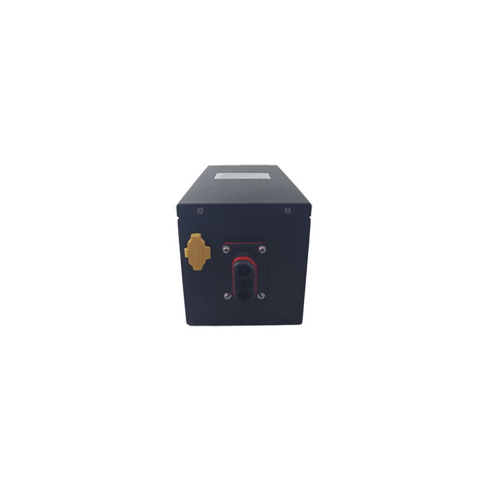
Connector selection is based on continuous and peak current, voltage, contact resistance, locking, polarity control, mating cycles, ingress exposure and installation space. Wire length, cable exit direction, pinout and strain relief should be approved on the mechanical drawing before prototype assembly.
Charging a 21700 Battery Pack
A multi-cell 21700 battery pack requires a charger matched to its series count, maximum charge voltage, approved charge current and control method. A charger intended for one loose 21700 cell is not suitable for a series-connected pack, and a charger should never be reused only because its connector fits.
Some equipment needs separate charge and discharge ports; other systems use one common port. A smart charger or docking station may exchange temperature, identification, enable or digital communication signals with the battery. These details must be agreed with the host-equipment team before BMS hardware and firmware are finalized.
Custom 21700 Battery Pack Specification Framework
| Item | Typical custom options | How it is confirmed |
|---|---|---|
| Nominal voltage | Approximately 7.2V / 7.4V to 96V nominal; other systems reviewed separately | Equipment voltage window, series count, charger and insulation requirements |
| Capacity | Approximately 5Ah to 300Ah, project-specific | Runtime, load profile, usable voltage range, space and weight |
| Cell format | Rechargeable 21700 cylindrical lithium-ion cells | Energy, power, temperature, cycle life and documentation needs |
| Configuration | Project-specific series-parallel cell layout | Voltage, capacity, current sharing, heat and mechanical envelope |
| BMS | Basic protection, balancing, fuel gauge or smart communication | Series count, current, sensors and host-equipment interface |
| Structure | Cell holder, heat-shrink, plastic case, metal case or sealed enclosure | Drawing, mounting, vibration, ingress and service requirements |
| Connector | Standard or project-specific power, charge and communication connectors | Current, voltage, locking, pinout, mating cycles and environment |
| Documentation | UN 38.3 planning and test summary, SDS/MSDS and application-specific compliance review | Final configuration, transport mode, equipment category and destination market |
These are design starting points rather than ready-made approved specifications. Continuous current, peak current, operating temperature, cycle life, enclosure rating and documentation are confirmed only after the selected cell and complete pack architecture have been reviewed.
Prototype and Validation Plan
A prototype should be tested inside the actual equipment whenever possible. A light-load capacity test confirms stored energy under one condition but does not prove compatibility with a motor controller, docking charger, cold start or repeated industrial duty cycle.
- Cell model, lot, voltage and internal-resistance inspection
- Series-group voltage, polarity and insulation verification
- Weld-process control and conductor inspection
- BMS protection, balancing, temperature and communication checks
- Capacity and delivered-energy testing at an agreed load
- Continuous and peak-load tests with voltage-sag recording
- Charge compatibility, cutoff behavior and charge-temperature testing
- Thermal mapping at cells, BMS, fuse, cables and connectors
- Fit, mounting, vibration, shock, drop or ingress tests where applicable
- Aging, final inspection, labeling and production traceability
Acceptance limits should be agreed before pilot production. Our battery quality-control process can be reviewed together with the project test plan so that prototype approval and repeat-production inspection use consistent criteria.
Production Consistency for OEM Projects
A successful engineering sample is only the first stage. Repeatable production also depends on an approved bill of materials, controlled cell sourcing, lot traceability, calibrated welding, BMS firmware control, assembly instructions and final-test records. Any change to the cell, BMS, connector or conductor can affect electrical performance and documentation scope.
For pilot and volume orders, useful controls include first-article approval, golden-sample comparison, defined substitution rules, serial or lot identification and agreed outgoing inspection data. These controls are especially important when several batteries will operate as part of one robot or equipment fleet.
Certification and Export Documentation
Compliance depends on the final battery configuration, application and destination market. UN 38.3 concerns transport testing for lithium cells and batteries; it is not a complete product-safety certification. IEC 62133-2 may be relevant to portable sealed lithium cells and batteries, while IEC 62619 may be considered for industrial applications. The correct route must be confirmed from the finished equipment category.
An SDS or MSDS communicates safety and handling information but is not a product certification. CE marking is based on the finished product and applicable European legislation; it is not automatically granted because an individual cell or battery has a transport report. Certification planning should begin before the production cell, BMS, enclosure and connector are frozen.
Information Needed for a Custom 21700 Battery Quote
Electrical requirements
- Nominal, minimum and maximum voltage
- Capacity, energy or target runtime
- Continuous and peak current with duration
- Charger output and required charging time
- Communication and fuel-gauge functions
Mechanical and project requirements
- Maximum dimensions or a 3D battery envelope
- Mounting, enclosure and cable-exit requirements
- Connector photo, part number and pinout
- Operating, charging and storage temperatures
- Prototype quantity, annual demand and destination market
If the project is replacing an existing battery, include photos of every side, the original label, connector and charger together with the equipment model. If the load data is unknown, equipment power information or a measured current trace can help define the prototype test.
Related Custom Battery Support
Review our complete custom battery pack engineering process, compare existing designs in the 21700 battery pack catalog, evaluate the smaller-cell alternative on our custom 18650 battery pack page, or send your voltage, current, runtime and size requirements for an engineering review.
Frequently Asked Questions
Why choose 21700 cells for a custom battery pack?
A suitable 21700 cell can provide more capacity per cell than many 18650 options, which may reduce cell and weld count for a given energy target. The benefit depends on available space, required current, thermal behavior, cost and cell supply.
What are the dimensions of a 21700 battery?
The name describes a cylindrical format approximately 21 mm in diameter and 70 mm long. Actual maximum dimensions and terminal details vary, so the mechanical design must use the datasheet for the selected cell model.
Is a 21700 battery always better than an 18650 battery?
No. A 21700 layout can reduce cell count in some high-energy packs, while smaller 18650 cells may fit narrow or irregular spaces more effectively. Compare complete pack size, weight, heat, connections, cost and supply continuity.
Can a 21700 battery pack support high current?
Yes, when the selected cell, parallel count, interconnects, BMS, wiring, connector and cooling are designed for the continuous and peak loads. Not every high-capacity 21700 cell is intended for high-current use.
Does a 21700 battery pack need a BMS?
A rechargeable multi-cell pack normally requires protection and monitoring appropriate to the application. BMS functions can include voltage, current and temperature protection, balancing, fuel gauging and CAN, RS485, UART or other communication.
Can the 21700 battery holder and enclosure be customized?
Yes. Cell holders, structural supports, heat-shrink, plastic cases, metal enclosures, mounting features and sealed housings can be designed around the approved cell matrix and equipment space.
What charger should be used for a 21700 battery pack?
Use a charger approved for the pack’s series count, maximum voltage, charge current and control method. A charger for one loose 21700 cell is not suitable for a multi-cell series pack, and connector fit alone does not confirm compatibility.
Can a custom 21700 battery pack reach 96V?
Yes, an approximately 96V nominal design can be reviewed, but maximum charged voltage, BMS architecture, insulation, connectors, fusing, enclosure and service access become more demanding as series count increases.
Which certifications and documents can be supported?
Support can include UN 38.3 transport-test planning and a test summary, SDS/MSDS, specifications, labels and inspection records for the approved configuration. IEC 62133-2, IEC 62619, CE-related or other requirements are evaluated according to the application and market.
What is needed before making a prototype?
Provide the voltage window, capacity or runtime, continuous and peak current, size limit, charger, connector, operating temperature, application, quantity and destination market. A device drawing and current profile make the review more accurate.
Engineering review note: Published voltage, capacity and application ranges are starting points. The production specification is confirmed only after the exact cell model, series-parallel layout, BMS, load profile, charger, enclosure, connector and validation plan have been approved together.