
A custom 24V LiFePO4 battery pack is designed around the machine rather than a fixed catalog case. Industrial equipment may run for long shifts, start motors repeatedly, recharge from an automatic dock and operate under vibration, dust or changing temperatures. The battery therefore has to coordinate cell capability, BMS current, charging, communication, enclosure strength, mounting and service access.
We develop project-specific 24V and 25.6V lithium iron phosphate battery systems for industrial instruments, compact AGV modules, mobile machines, control equipment, inspection devices and backup power. Capacity, cell format, continuous current, peak current, connector, housing and communication are selected from the real operating profile instead of copied from a generic model.
This guide explains the 8S voltage architecture behind a 24V LiFePO4 battery, how capacity and current are calculated, what a motor-driven machine needs from the BMS, how charging and communication are integrated, and which tests and documents should be planned before production.
Why a 24V LiFePO4 Battery Is Normally Rated at 25.6V
A standard 24V-class LiFePO4 battery normally uses eight lithium iron phosphate cell groups connected in series. This is called an 8S configuration. With each cell group rated at approximately 3.2V nominal, the completed pack has a nominal voltage of about 25.6V. For this reason, “24V LiFePO4 battery” and “25.6V LiFePO4 battery” commonly describe the same system voltage class.
| Voltage term | Typical 8S LiFePO4 value | Engineering meaning |
|---|---|---|
| Nominal voltage | Approximately 25.6V | Used for energy, power and runtime calculations |
| Maximum charge voltage | Commonly within 28.8–29.2V, subject to the approved cells and BMS | The charger and machine input must accept the complete voltage window |
| Discharge range | Defined by cell limits, equipment cutoff and BMS settings | There is no universal low-voltage setting for every 24V pack |
| Series configuration | Eight cell groups in series | Parallel cells or larger cells increase capacity and current without changing nominal system voltage |
The figures above are design references, not universal charger settings. Final limits follow the selected cell specification, BMS thresholds, charger behavior, load and required service life. A seven-series NMC lithium-ion pack may also be sold as “24V,” but its voltage profile and charging requirements differ from an 8S lithium iron phosphate battery.
The broader terms 24V lithium battery and “24 volt battery” do not identify the cell chemistry or charging profile. An OEM specification should state 8S LiFePO4 or 25.6V LiFePO4 clearly so that the cell count, charger, BMS and equipment limits are not confused with an NMC system.
Why Industrial Equipment Uses 24V Instead of 12V
For the same electrical power, increasing system voltage reduces current. Lower current can reduce conductor demand and resistive loss, which is valuable in machines with motors, pumps, actuators, controllers or long cable runs. The benefit must still be balanced against the equipment voltage limits, BMS architecture, charger and connector rating.
For example, a 1.2kW load draws approximately 46.9A at 25.6V nominal:
1,200W ÷ 25.6V = 46.9A
The same 1.2kW load at 12V would draw about 100A before accounting for efficiency or voltage variation. This example explains the relationship only. Actual current changes throughout discharge and must include startup pulses, controller efficiency, cable loss and duty cycle.
A 24V system can be a practical middle ground for equipment that needs more power than a small 12V battery can comfortably deliver but does not require a high-voltage architecture. It is commonly found in compact mobile machines, low-voltage automation, instrumentation and backup systems.
Best-Fit Applications for a Custom 24V Battery Pack
A custom battery is most useful when the electrical interface, mechanical space or operating duty cannot be met by a standard replacement battery. Typical applications include:
- Compact AGVs, autonomous carts and mobile robot subsystems
- Industrial instruments, data-acquisition equipment and inspection devices
- Floor-care machines, pumps, actuators and other low-voltage motor equipment
- Control cabinets, PLC backup modules and emergency power systems
- Portable test, maintenance and field-service equipment
- Solar-powered monitoring, lighting and remote-control systems
- Communications equipment and small DC UPS installations
- OEM machinery requiring a specific case, connector or communication protocol
Application names alone do not determine the battery. Two compact AGVs may use the same nominal voltage but have different wheel motors, slopes, payloads, regenerative current, charging docks and shift lengths. The load profile and machine interface must be reviewed before capacity and BMS current are frozen.
Capacity, Energy and Runtime Calculation
Battery capacity is usually stated in ampere-hours, but watt-hours provide a clearer view of available nominal energy. For an 8S LiFePO4 pack:
Nominal energy (Wh) = 25.6V × capacity (Ah)
| Battery capacity | Approximate nominal energy | Typical design question |
|---|---|---|
| 24V 20Ah | 512Wh | Can the pack supply the peak load as well as the required runtime? |
| 24V 50Ah | 1.28kWh | Does the selected cell format fit the machine compartment? |
| 24V 100Ah | 2.56kWh | Are enclosure, mounting and charging time acceptable? |
| 24V 200Ah | 5.12kWh | How will cell support, heat, service and high current be managed? |
| 24V 300Ah | 7.68kWh | Does the final machine need modular construction or a larger industrial housing? |
A 24V 100Ah LiFePO4 battery therefore stores approximately 2.56kWh of nominal energy. Usable energy is lower and depends on discharge current, temperature, BMS cutoff, machine shutdown voltage, conversion efficiency, aging and the reserve required by the duty cycle.
For meaningful runtime estimation, provide average power, peak power, operating modes, time spent in each mode and charging opportunities during the shift. A machine that returns to a charging dock between tasks may need a different capacity and charge-rate strategy from equipment expected to run continuously for eight hours.
Selecting Cylindrical or Prismatic LiFePO4 Cells
The pack can use cylindrical, prismatic or another approved LiFePO4 cell format where appropriate. Selection is based on energy, current, shape, mechanical environment, temperature, cycle target and production method rather than a preference for one format.
- Cylindrical cells: Formats such as 26650 and 32700 can support flexible layouts and repeatable assembly. More parallel connections may be required at higher capacities.
- Prismatic cells: Larger cells can reduce cell count in 100Ah, 200Ah and other higher-capacity packs. Terminal fastening, cell compression, insulation and structural retention require controlled design.
- Pouch cells: These can support thin or special-shaped packs where justified, but swelling allowance, tab support and enclosure protection need careful engineering.
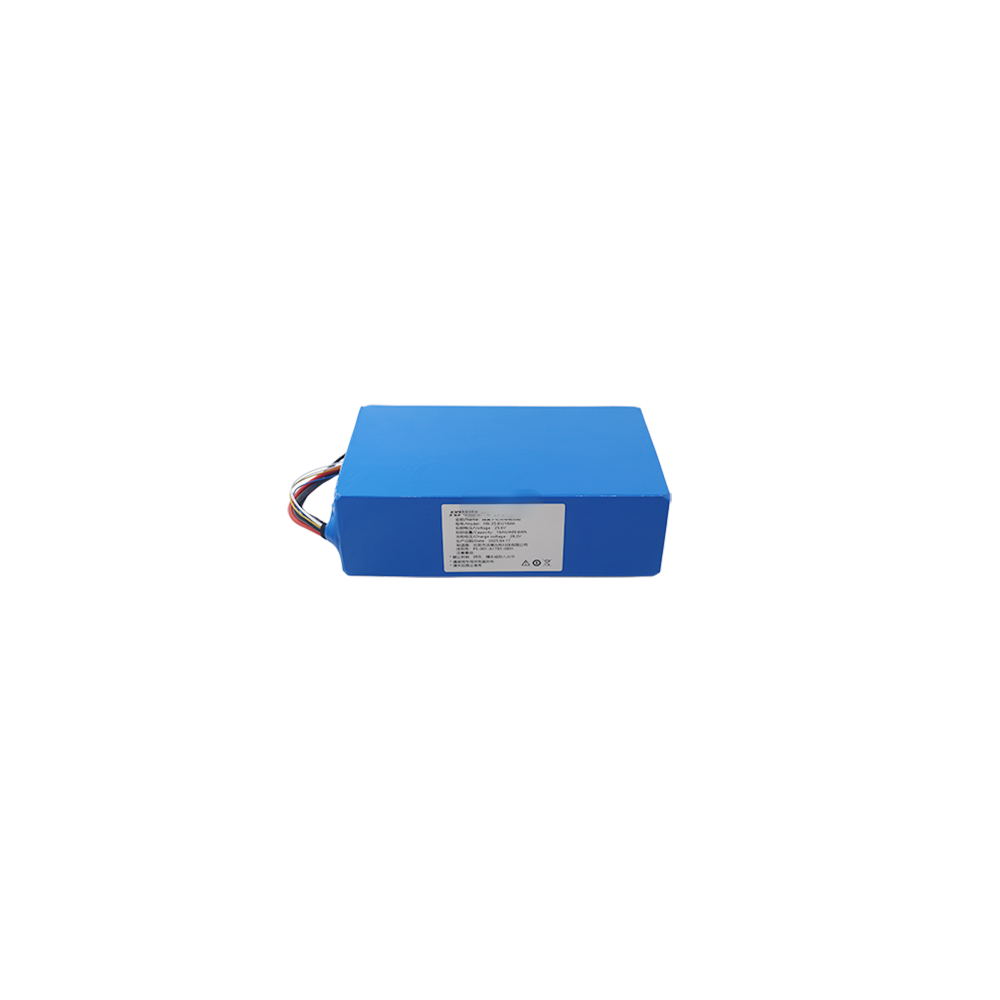
Approved cells should be grouped by defined voltage, capacity and internal-resistance criteria. Cell quality alone does not guarantee pack reliability. Busbars, welds, bolts, insulation, harness routing, vibration supports and thermal paths must also be designed for the specified current and working environment.
BMS Design for Continuous, Peak and Regenerative Current
The 24V LiFePO4 battery BMS monitors eight series cell groups and manages pack-level protection. Its discharge rating must be based on the machine load, not just the battery capacity. Motor-driven equipment can draw a short startup or stall current several times higher than normal running current, while deceleration may return regenerative current to the battery.
| Current requirement | Information needed | Design effect |
|---|---|---|
| Continuous discharge | Normal current or power and operating duration | Controls cell loading, BMS conduction loss, busbars, cables and thermal rise |
| Peak discharge | Peak current, pulse duration and repetition rate | Controls voltage sag and whether the BMS allows the motor or controller to start |
| Stall or abnormal load | Controller limit and expected fault duration | Helps coordinate BMS overcurrent protection with machine protection |
| Charge current | Charger output and available charging time | Determines charge MOSFET, cell charge rate and connector requirement |
| Regenerative current | Maximum returned current, duration and battery state of charge | Affects charge-current limits, high-SOC control and communication with the machine |
| Inrush current | Controller input capacitance or measured startup surge | May require precharge or an agreed wake-up sequence |
Depending on the current and system architecture, switching can use a MOSFET-based BMS or a project-specific contactor arrangement. Protection functions may include cell overvoltage, undervoltage, discharge overcurrent, charge overcurrent, short circuit, high temperature, low-temperature charging protection and cell balancing.
The equipment must also respond safely when the BMS limits or disconnects the battery. A protective shutdown should not create uncontrolled motion, corrupt data or trap the machine in an unsafe location. Fault response, restart conditions and emergency behavior are part of the system interface.
CAN, RS485 and Smart BMS Communication
A smart BMS can send battery data to an AGV controller, charger, display, PLC or supervisory system. Available interfaces can include CAN, RS485, UART or a project-specific protocol. Communication is useful when the machine must display state of charge, reduce power before shutdown, coordinate charging or record battery faults.
- Pack voltage, current and calculated state of charge
- Individual cell-group voltages
- Temperature sensor values
- Allowable charge and discharge current
- Warnings, protection events and fault codes
- Charge enable, discharge enable and contactor status where applicable
- Cycle count, remaining capacity or state-of-health information
- Serial number, software version and service records
“CAN communication” is not a complete requirement. The message identifiers, bit definitions, scaling, update rate, timeout behavior, termination resistance and fault response must be agreed between the battery and machine teams. If an existing controller is used, provide its protocol document or DBC file before BMS software is frozen.
Enclosure, Mounting, Connector and Cable Design
Industrial battery packaging must protect the cells and electronics while allowing safe assembly and service. Housing options include PVC shrink wrap for protected internal compartments, molded plastic cases, fabricated metal enclosures and project-specific sealed housings. The choice depends on mass, impact, vibration, ingress, corrosion, thermal conditions and available mounting space.
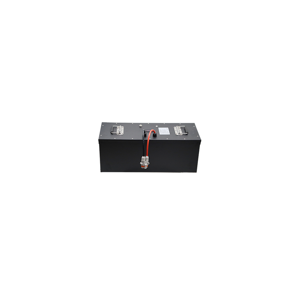
- Mounting: Confirm orientation, fastener positions, support surfaces, center of gravity and vibration direction.
- Service access: Position fuses, switches, connectors and communication ports where trained personnel can reach them safely.
- Power connection: Select terminals or plugs for current, contact resistance, mating cycles and environmental exposure.
- Signal connection: Separate communication, temperature, wake-up and interlock wiring from high-current conductors where practical.
- Cable design: Confirm conductor size, insulation rating, bend radius, strain relief, polarity marking and exit direction.
- Protection: Coordinate battery fuse, BMS protection, machine protection and available fault current.
Before sampling, provide a compartment drawing, 3D model or measured installation envelope. Connector photos are useful, but the manufacturer and exact part number are better because visually similar connectors can have different keys, contacts or current ratings.
Selecting a 24V LiFePO4 Battery Charger
A 24V LiFePO4 battery charger must match the approved 8S pack voltage and maximum charge current. Many 25.6V packs use a final charge voltage within the 28.8–29.2V range, but the exact value follows the selected cells, BMS and life-cycle target. Charger behavior when the BMS disconnects or reconnects must also be tested.
- Manual AC charger: Confirm input region, output voltage, current, connector, termination and indicator behavior.
- Automatic charging dock: Define contact sequence, communication, alignment, maximum current and machine wake-up logic.
- Solar controller: Use an approved LiFePO4 profile and review absorption, float, recovery and temperature settings.
- Vehicle or generator supply: A controlled DC/DC charger may be required to prevent excessive current or unsuitable voltage.
- UPS or standby charger: Verify continuous float behavior, restart thresholds, alarms and expected standby life.
Charging time is determined by usable capacity, initial state of charge, charger current, cell charge limit and the constant-voltage phase. A larger charger is not automatically better; its current must remain within the cell, BMS, connector and thermal limits.
Replacing a 24V Lead-Acid Battery System
A 24V LiFePO4 battery can replace a 24V lead-acid pack or two 12V lead-acid batteries connected in series in many machines, but it should not be treated as a universal drop-in replacement. The chemistries have different voltage curves, charging behavior, temperature limits and protective responses.
| Compatibility item | What must be checked |
|---|---|
| Machine voltage window | The controller accepts the maximum charged voltage and operates through the LiFePO4 discharge range |
| Existing charger | Output voltage, current, float, equalization, desulfation and restart behavior suit the approved pack |
| Motor current | Continuous, startup, stall and regenerative currents remain within cell and BMS limits |
| State-of-charge display | A lead-acid voltage gauge may not estimate the flatter LiFePO4 discharge curve accurately |
| Physical installation | Case size, terminals, cable exit, hold-down and machine balance remain acceptable |
| Low-temperature charging | The BMS, charger or heater prevents charging outside the selected cell limits |
| BMS disconnect | The machine shuts down and restarts safely after a protection event |
| Series or parallel expansion | The battery and BMS are specifically approved for the intended configuration |
LiFePO4 may provide lower mass, a flatter discharge voltage and longer cycle potential, but these advantages depend on correct system integration. If the original charger uses lead-acid equalization or desulfation pulses, it should not be assumed compatible.
Vibration, Ingress and Temperature Requirements
Mobile equipment can expose the battery to repeated shock, vibration and connector movement. Cell supports, busbars, terminal fasteners, BMS mounting and heavy cables must be restrained so that the electrical connections do not carry mechanical loads. Validation should reproduce the installation orientation and mounting method whenever possible.
Outdoor or wash-down equipment requires a defined ingress target for the complete assembly, including seams, fasteners, vents, cable glands, switches and connectors. Sealing alone is not enough: condensation, pressure change, heat rejection and corrosion also require review.
Charging and discharging temperature limits must be considered separately. Many standard LiFePO4 cells should not be charged below 0°C unless permitted by the cell manufacturer under defined conditions. Low-temperature charge cutoff, controlled heating, charger coordination or an approved low-temperature cell can be considered where required. Published temperature capability is confirmed only for the final cell, BMS, enclosure and test condition.
Custom 24V LiFePO4 Battery Specification Framework
| Item | Project-specific range or options | Confirmation method |
|---|---|---|
| Nominal voltage | 25.6V, commonly described as 24V LiFePO4 | 8S cell configuration and machine voltage review |
| Capacity | Typically 20Ah to 300Ah | Runtime, load profile, space, mass and charging opportunity |
| Nominal energy | Approximately 512Wh to 7.68kWh across the stated range | Voltage × capacity followed by usable-energy testing |
| Cell format | Cylindrical, prismatic or pouch where suitable | Current, packaging, thermal, vibration and cycle target |
| Current | Project-specific continuous, peak, charge and regenerative ratings | Machine load data and prototype measurement |
| BMS | Basic protection or smart BMS with monitoring and control | Threshold, interface and fault-response specification |
| Communication | CAN, RS485, UART or project-specific protocol | Protocol document, DBC file and integration testing |
| Enclosure | Shrink wrap, plastic, metal or sealed industrial housing | Mechanical drawing and environmental target |
| Connector | Terminals, industrial power plugs, signal connectors or custom harness | Current, pinout, mating, ingress and service review |
| Documentation | Specification, drawings, UN 38.3 planning, test summary and SDS/MSDS support | Final configuration, application and destination market |
These values describe a custom engineering range rather than universal stocked models. The production specification is released only after the cell, BMS, enclosure, connector, charger, communication and validation requirements are approved.
Prototype and Production Validation
Industrial projects should begin with representative samples and an agreed acceptance plan. Useful validation stages include:
- Cell and material inspection: Verify approved model, batch information, voltage, resistance, appearance and critical components.
- Assembly inspection: Check polarity, series connections, welds or fasteners, insulation, busbars, cable routing and workmanship.
- BMS functional test: Confirm cell measurement, balancing, voltage protection, current protection, temperature protection and fault recovery.
- Capacity and energy test: Measure delivered capacity and energy under an agreed charge and discharge condition.
- Continuous-load test: Record cell, BMS, busbar, cable and connector temperatures at normal machine current.
- Peak and startup test: Verify voltage sag and BMS behavior using the real motor pulse or an equivalent programmed profile.
- Regeneration and charging test: Confirm returned current, high-state-of-charge behavior, charger communication and dock sequence.
- Communication test: Validate CAN or RS485 messages, timeout handling, alarms, state-of-charge display and fault response.
- Machine integration test: Run representative shifts, slopes, payloads and stop-start cycles in the intended equipment.
- Environmental test: Add vibration, shock, thermal cycling, ingress or corrosion testing when required by the application.
Acceptance criteria should be agreed before pilot production. Changing the cell model, BMS hardware, connector or enclosure after testing may affect performance, mechanical results and export documentation.
Certification and Export Documentation Planning
Compliance depends on the final pack, application and destination. UN 38.3 addresses lithium-cell and battery transport testing; it is not a complete product-safety certification for the finished machine. Portable applications may require evaluation against IEC 62133-2 where applicable, while industrial secondary lithium batteries may be evaluated against IEC 62619 or another application-specific standard.
Documentation support can include an approved specification, mechanical drawing, wiring information, BMS communication document, label data, inspection records, UN 38.3 test planning and test summary, and SDS/MSDS. CE, CB, UL or other certification claims are confirmed only after the responsible manufacturer, applicable standard, final configuration and test route are agreed. They should not be promised solely from a preliminary voltage and capacity range.
Information Needed for a Custom 24V Battery Quote
- Machine type and battery function
- Required capacity, energy or working hours per charge
- Average current or power
- Peak current, startup duration, stall limit and repetition rate
- Regenerative current where applicable
- Charger model, voltage, current and available charging time
- Battery compartment dimensions, weight limit and installation orientation
- Mounting points, cable-exit direction and service-access requirement
- Power connector, signal connector, cable length and pin definition
- CAN, RS485, UART or other communication protocol
- Operating temperature, storage temperature and low-temperature charging requirement
- Vibration, shock, dust, water and corrosion targets
- Destination market and applicable test or certification requirement
- Prototype quantity, annual forecast and project schedule
If the project replaces an existing battery, also provide photos of its label, terminals, wiring, charger and installation compartment. For an AGV or motor-driven machine, a controller datasheet and measured startup-current trace are especially useful.
Related Custom Battery Support
Review our complete custom battery pack engineering service, compare available models in the battery product catalog, explore equipment requirements under battery solutions, learn how packs are checked through our battery quality control process, or send your 24V battery requirements for an engineering review.
Frequently Asked Questions
Is a 24V LiFePO4 battery actually 25.6V?
Usually yes. A typical 24V-class LiFePO4 pack uses eight 3.2V nominal cell groups in series, producing approximately 25.6V nominal. The equipment and charger must accept the complete operating voltage range, not only the nominal value.
What charger voltage is used for a 24V LiFePO4 battery?
Many 8S LiFePO4 batteries use a maximum charge voltage within 28.8–29.2V, but the approved value depends on the selected cells, BMS and life-cycle target. Use the charger specified for the final battery rather than a generic 24V charger.
Is a custom 24V battery suitable for motor loads?
Yes, when the cells, BMS, busbars, cables and connector are selected for continuous current, startup current, stall behavior and regenerative current. A motor nameplate alone may not show the actual battery pulse requirement.
Can the pack use CAN or RS485 communication?
Yes. A smart BMS can support CAN, RS485, UART or another agreed interface. The protocol, message map, update rate, timeout behavior and machine fault response must be defined during development.
How much energy is in a 24V 100Ah LiFePO4 battery?
A 25.6V 100Ah battery has approximately 2,560Wh, or 2.56kWh, of nominal energy. Usable energy depends on current, temperature, machine cutoff, BMS settings, efficiency, aging and required reserve.
Can it replace two 12V lead-acid batteries in series?
It can in many systems, but compatibility must be checked for maximum voltage, charger profile, motor current, low-voltage cutoff, terminals, enclosure, temperature and BMS-disconnect behavior. It is not automatically a drop-in replacement.
Can 24V LiFePO4 batteries be connected in series or parallel?
Only when the battery and BMS are specifically approved for the intended connection. Series use changes voltage and insulation requirements; parallel use changes current sharing, available fault current and protection coordination.
Can you make a metal or waterproof enclosure?
Yes. Metal, plastic, shrink-wrapped and sealed structures can be developed according to the mounting and environmental requirement. A waterproof claim is confirmed only for the final case, seals, connectors, cable glands, vents and test condition.
Which export documents can be supported?
Depending on the approved configuration and destination, support can include UN 38.3 test planning and test summary, SDS/MSDS, specifications, drawings, labels and inspection records. CE, CB or other product-safety routes are evaluated separately for the final application.