
A custom high-voltage lithium battery pack is an electrical, mechanical and control-system project rather than a group of cells connected in series. Once a battery system moves into higher DC voltage and power levels, the design must coordinate cell selection, module architecture, insulation, contactors, precharge, fusing, current measurement, thermal management, communication and safe service access.
We develop project-specific LiFePO4 and NMC battery systems for industrial vehicles, mobile equipment, electric platforms, energy storage and other OEM applications. Typical projects begin around 96V and may extend to 800V or higher, but voltage alone does not define the design. The required power, peak current, short-circuit energy, charging source, operating environment and applicable safety standard must be reviewed together.
The objective is not simply to reach a nominal voltage. A successful high-voltage battery must start the connected inverter or motor controller correctly, remain inside the equipment voltage window throughout discharge, isolate faults, control temperature and allow the finished machine to be assembled and maintained without exposing operators to avoidable electrical risk.
What Makes a High-Voltage Battery Pack Different?
A low-voltage battery can often use one compact protection board and one main connector. A high-voltage battery normally requires several coordinated subsystems. As series cell count increases, the BMS must measure more cell groups, the insulation system must withstand a larger potential difference and switching the DC bus becomes more demanding.
- More series-connected cells: Cell-voltage measurement, balancing and harness routing become more complex.
- Higher stored energy: Fuse coordination, enclosure strength and fault containment require early review.
- High-voltage switching: Main contactors, precharge components and discharge paths must match the DC bus and load capacitance.
- Insulation coordination: Creepage, clearance, connector touch protection, cable routing and isolation monitoring become system-level requirements.
- Thermal control: Heat generated by cells, busbars, fuses and contactors must stay within validated limits.
- Service safety: A service disconnect, interlock loop, warning labels and access procedure may be needed.
Best-Fit Applications
Custom high-voltage battery packs are best suited to OEM equipment whose voltage, power, packaging or communication requirements cannot be met by an off-the-shelf battery. Common applications include:
- Industrial vehicles, automated carriers and heavy mobile machinery
- Electric construction, agricultural and material-handling equipment
- Port machinery, ground-support equipment and special-purpose vehicles
- Mobile energy storage, high-power backup and DC power platforms
- Electric propulsion equipment and OEM EV subsystems
- Robotics or autonomous platforms with high-power inverter loads
- Industrial systems requiring modular 96V, 120V, 144V, 300V, 400V or higher-voltage battery architecture
The same nominal voltage can represent very different projects. A 400V system delivering short intermittent power has different cells, cooling and contactor requirements from a 400V battery operating continuously for several hours. Application data must therefore be reviewed before chemistry and module size are selected.
Define the Electrical Requirements Before Designing Modules
The most useful starting point is the complete voltage and load window of the equipment. Nominal voltage should never be provided without the inverter, motor controller, DC/DC converter or charger limits.
| Requirement | Information to provide | Why it affects the design |
|---|---|---|
| Voltage window | Nominal voltage, maximum charged voltage and minimum equipment operating voltage | Determines series cell count, BMS limits, charger voltage and inverter compatibility |
| Continuous power | Normal kW demand, operating duration and duty cycle | Determines cell loading, conductor size, contactor rating and cooling demand |
| Peak power | Peak kW or current, pulse duration and repetition frequency | Controls voltage-sag allowance, cell configuration and peak-current protection |
| Regenerative current | Maximum regeneration current, duration and operating state of charge | Affects charge-current limits, high-SOC control and BMS communication |
| Load capacitance | Inverter or DC-link capacitance and acceptable precharge time | Determines precharge resistor, relay and control sequence |
| Charging interface | Charger model, voltage/current range, connector and communication protocol | Defines charge control, interlocks and compatibility testing |
| Environment | Temperature, altitude, humidity, vibration, dust, water and installation orientation | Affects insulation, cooling, enclosure, derating and validation plan |
Modular Battery Architecture and Voltage Scaling
A modular structure can make a high-voltage pack easier to assemble, monitor and service. Cells are arranged into repeatable battery modules, and the modules are then connected in series or series-parallel to reach the system voltage and energy target. The correct module voltage is selected around cell count, mechanical handling, BMS channel count, service procedure and transport strategy.
Modularity does not mean that any module can be added later without a new review. Increasing series count changes maximum voltage, insulation stress, contactor requirements, charger compatibility and BMS configuration. Increasing parallel capacity changes available fault current, busbar current and fuse coordination. Every final configuration therefore receives its own approved electrical drawing and bill of materials.
Centralized Pack
A centralized layout may suit a compact battery with a manageable number of cell-monitoring channels and short sensing harnesses. It can reduce controller count but may limit physical scaling.
Distributed Modules
A distributed architecture uses module monitoring units linked to a master controller. It can simplify long-series measurement, modular assembly and fault localization in larger packs.
LiFePO4 or NMC for a High-Voltage Lithium Battery?
LiFePO4 and NMC can both be used in a custom high-voltage lithium battery pack, but the choice must follow the application rather than a single marketing advantage.
- LiFePO4: Often selected where cycle life, thermal stability and frequent industrial use are priorities. Its lower cell voltage usually requires more series cells for the same system voltage.
- NMC: Often selected where energy density, lower pack mass or compact packaging is more important. Cell selection and thermal-control strategy must match the required power and operating environment.
Cell format can include cylindrical, prismatic or pouch cells where appropriate. The final choice is evaluated using validated discharge data, charge limits, cycle target, thermal behavior, supplier consistency, mechanical support and required documentation. Chemistry name alone is not enough to predict pack safety or service life.
High-Voltage Battery Management System Architecture
A high-voltage battery management system supervises cell groups and coordinates the pack with the charger, inverter and vehicle or machine controller. For larger systems, the BMS may use cell-monitoring units at module level and a master BMS for pack-level decisions.
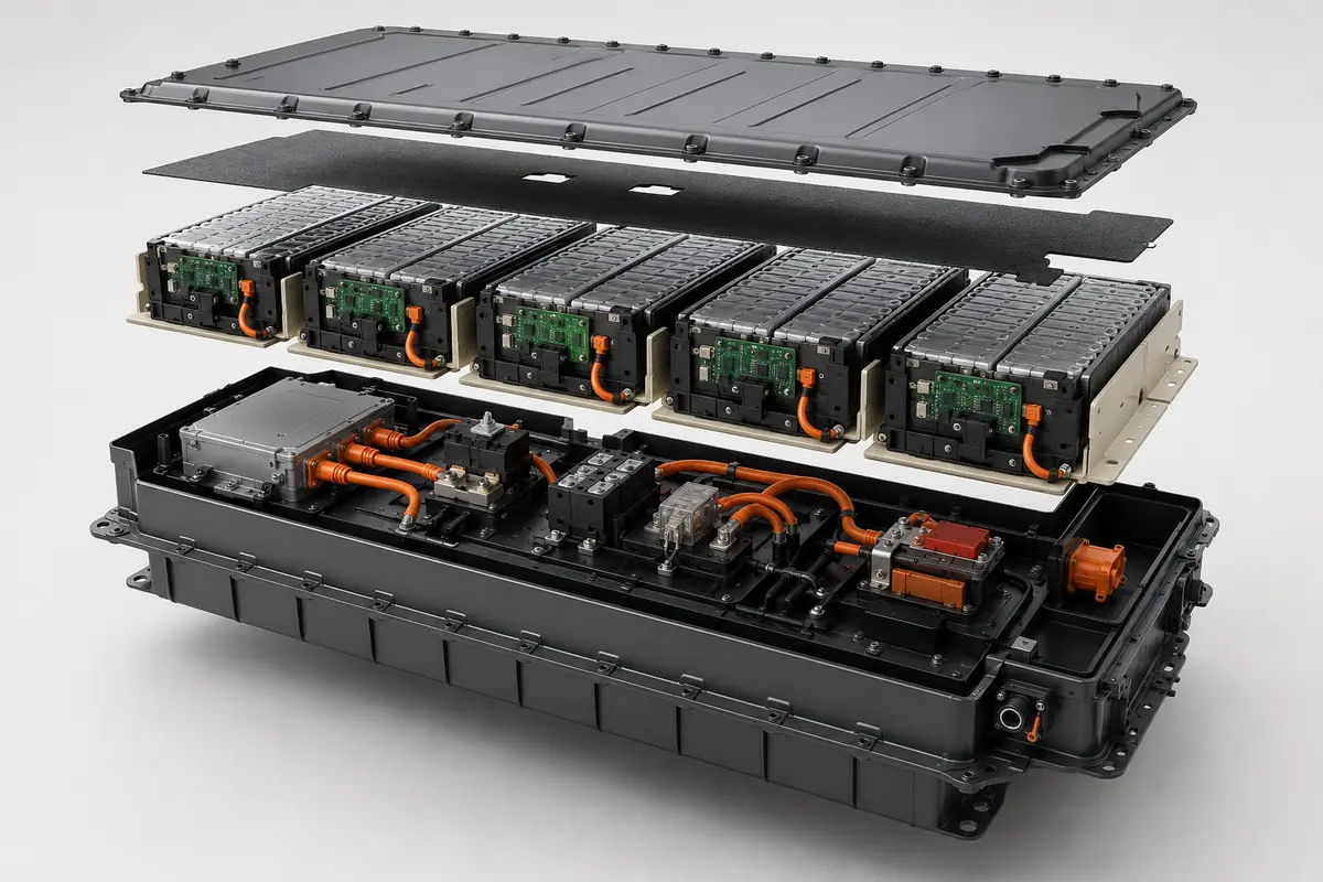
Depending on the project, BMS functions may include:
- Cell-voltage and module-voltage measurement
- Multiple temperature sensors and thermal-limit control
- Passive or active balancing where justified by the application
- Pack-current measurement and state-of-charge estimation
- State-of-health and event-history functions where required
- Contactor, precharge and discharge-circuit control
- Insulation-monitoring interface and high-voltage interlock supervision
- Charge, discharge and regenerative-current limits
- Fault classification, warning, derating and shutdown logic
- CAN, CAN FD, RS485 or other project-specific communication
The BMS cannot correct an unsuitable cell, undersized busbar or inadequate cooling system. Protection thresholds must be built from the selected cell limits and then validated at module and pack level. Communication messages, timeout behavior and fault responses should be agreed with the equipment-control team before prototype software is frozen.
Contactors, Precharge, Fuses and Service Isolation
The high-voltage protection chain must be treated as one coordinated circuit. Main positive and negative contactors connect the battery to the DC bus. A precharge path limits inrush current while the load capacitance charges. A correctly selected fuse interrupts specified overcurrent conditions, while a service disconnect creates an intentional break for authorized maintenance.
- Main contactors: Selected for maximum DC voltage, continuous current, making/breaking conditions and expected switching life.
- Precharge circuit: Designed around actual DC-link capacitance, voltage and target precharge time, with fault detection for incomplete or abnormal precharge.
- Primary fuse: Coordinated with conductor capability, contactors, cell fault current and downstream protection rather than chosen from normal current alone.
- Service disconnect: Positioned so trained personnel can create a defined electrical separation during approved service work.
- HVIL: A high-voltage interlock loop can detect an opened connector, cover or service device and trigger the approved shutdown response.
- Isolation monitoring: May be required to detect loss of insulation between the high-voltage circuit and chassis or accessible conductive parts.
Insulation, Creepage, Clearance and High-Voltage Connections
High-voltage insulation must be designed around the maximum working voltage, transient conditions, pollution level, material group, altitude and applicable standard. The enclosure should prevent unintended contact with energized parts, while cable entries, busbar supports and sensing harnesses must remain secure through vibration and thermal cycling.
Engineering review commonly includes:
- Creepage and clearance distances across busbars, circuit boards and structural components
- Dielectric withstand and insulation-resistance test conditions
- Touch-safe high-voltage connectors and correctly rated orange HV cable where required
- Connector keying, polarity control and secondary locking
- Shielding and grounding strategy for communication and power cables
- Routing separation between high-voltage conductors and low-voltage sensing circuits
- Condensation, contamination, coolant leakage and altitude effects
Sealing the enclosure does not automatically solve insulation or thermal problems. A sealed design can trap heat and moisture, so ingress protection, pressure equalization, cooling and service access must be coordinated.
Battery Thermal Management and Cooling
A battery thermal management system keeps cell and component temperatures within the validated operating window and reduces temperature variation across modules. Cooling requirements are determined from measured or modeled heat generation at the actual duty cycle.
Possible strategies include passive conduction to the enclosure, forced-air cooling, liquid-cooling plates or a project-specific combination. Cold-climate projects may also require controlled heating before charging or high-power operation. The selected method depends on cell heat generation, available airflow or coolant, ambient temperature, allowable noise, enclosure rating and maintenance plan.
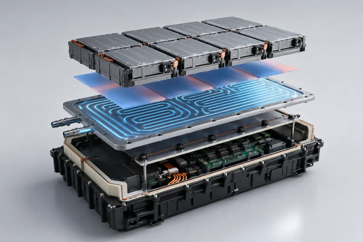
Thermal validation should measure representative cold and hot cell locations as well as busbars, fuses, contactors and power connectors. A low average temperature is not enough if one module or connection develops a local hot spot.
Why System Voltage Changes Current and Conductor Design
For the same electrical power, a higher operating voltage can reduce current. This can help reduce conductor current demand, but it increases insulation and high-voltage switching requirements.
Illustrative power example:
A 60kW load at 400V draws approximately:
60,000W ÷ 400V = 150A
The same 60kW load at 96V draws approximately:
60,000W ÷ 96V = 625A
Actual pack current changes with battery voltage, efficiency, transient load and operating conditions. These values explain the relationship only; they are not conductor, fuse or contactor selections.
This is why a 96V battery can still be a very high-current system, while an 800V battery may operate at lower current for the same power. Both require project-specific protection and validation.
Mechanical Structure and Service Access
The enclosure carries modules, busbars, contactors, cooling components and control electronics while maintaining electrical separation. Its structure should be reviewed against vibration, shock, lifting, mounting, ingress and maintenance requirements.
- Module retention and compression appropriate to the selected cell format
- Defined lifting points, mounting points and installation orientation
- Protected routing for high-voltage cables, sensing harnesses and coolant lines
- Serviceable placement of fuses, disconnects and control components
- Barriers between energized conductors and accessible areas
- Pressure relief or venting strategy where required by the risk assessment
- Corrosion-resistant materials for outdoor, marine or industrial use
Battery space, airflow, cable route, charger interface and service method should be reviewed before the equipment frame is finalized. Designing the machine first and fitting the battery afterward often creates avoidable cable bends, poor cooling and inaccessible service components.
Custom High-Voltage Battery Specification Framework
| Item | Project-specific options | How it is confirmed |
|---|---|---|
| Voltage | Typically 96V to 800V+ according to equipment voltage window | Cell-count calculation, charger and load-interface review |
| Energy and capacity | Defined in kWh and Ah from runtime, load profile and usable SOC window | Energy calculation followed by prototype discharge validation |
| Chemistry | LiFePO4 or NMC with cylindrical, prismatic or pouch formats where suitable | Cell-data review, supplier approval and application testing |
| Architecture | Centralized pack or modular series-connected battery system | Electrical schematic, mechanical drawing and service review |
| BMS | Cell monitoring, balancing, current limits, contactor control and communication | Hardware/software validation and fault-injection testing |
| High-voltage components | Contactors, precharge, fuse, service disconnect, HVIL and isolation interface | Component coordination and system sequence testing |
| Thermal management | Passive, forced-air, liquid cooling or controlled heating where required | Temperature mapping at specified duty cycle and environment |
| Communication | CAN, CAN FD, RS485 or project-specific interface | DBC/message review and equipment integration test |
| Enclosure | Industrial housing with project-specific ingress, vibration and mounting targets | Drawing approval and applicable environmental testing |
| Documentation | UN 38.3 planning, test summary, SDS/MSDS and application-specific evaluation | Confirmed from final configuration, destination and equipment category |
Prototype and High-Voltage Battery Validation
A high-voltage prototype should be validated as a complete system, not only as individual modules. The test plan is defined from the application risk assessment and may include:
- Cell and module checks: Confirm voltage consistency, temperature measurement, balancing and module wiring.
- Insulation tests: Verify insulation resistance, dielectric performance and isolation-monitor response under agreed conditions.
- Precharge sequence: Measure DC-bus rise time and confirm correct response to incomplete, delayed or abnormal precharge.
- Contactor operation: Confirm opening, closing, weld detection and fault response across intended operating states.
- Load testing: Measure voltage sag, temperature and delivered energy at continuous and peak load profiles.
- Charge and regeneration: Validate charger communication, charge limits and regenerative-current control.
- Thermal mapping: Record cell, busbar, fuse, contactor and connector temperatures under the required duty cycle.
- Communication faults: Test message timeout, sensor faults, disconnected modules and approved derating or shutdown behavior.
- Environmental tests: Add vibration, shock, thermal cycling, ingress, corrosion or altitude testing where applicable.
Acceptance criteria should be agreed before pilot production. Useful records include pack voltage, individual cell groups, current, temperatures, insulation value, contactor state, BMS warnings, fault events and delivered energy.
Certification and Export Documentation Planning
Compliance is determined by the final battery configuration, application and destination market. UN 38.3 addresses transport testing for lithium cells and batteries, but it is not a complete product-safety certification. Industrial lithium batteries may be evaluated against IEC 62619 where applicable. Electrically propelled road-vehicle projects may instead require standards and regulations such as ISO 6469, UL 2580 or UNECE R100, depending on the vehicle and market.
CE marking is based on the final product and applicable European legislation; it is not automatically granted because a battery has UN 38.3 documents. CB Scheme planning also requires an applicable IEC standard and certification route. These targets should be confirmed before cell, BMS, contactor, enclosure and cooling designs are frozen.
Depending on the project, documentation support can include an approved specification, drawings, BMS communication information, UN 38.3 test planning and test summary, SDS/MSDS, labels, inspection records and project-specific reports. Any certification claim is confirmed only after the final test scope and battery configuration are approved.
Information Needed for a Custom Design
For an efficient engineering review and quotation, provide as many of the following items as possible:
- Application and equipment type
- Nominal, maximum and minimum operating voltage
- Required energy in kWh, capacity in Ah or target runtime
- Continuous power, peak power, pulse duration and duty cycle
- Maximum charge current and regenerative-current profile
- Inverter, motor controller, DC/DC converter and charger information
- Installation space, weight limit, mounting and cable exit requirements
- Cooling source, coolant information or available airflow
- Operating temperature, storage temperature, altitude and ingress target
- Communication protocol, DBC file or required CAN messages
- Applicable market, certification target and test specification
- Prototype quantity, production forecast and project schedule
Related Custom Battery Support
Review our complete custom battery pack engineering service, compare available high-voltage battery systems, learn how prototypes and production packs are checked through our battery quality control process, or send your voltage, power and installation requirements for an engineering review.
Frequently Asked Questions
Can a custom high-voltage battery exceed 800V?
Yes, a project above 800V can be reviewed, but feasibility depends on maximum charged voltage, insulation coordination, contactors, connectors, BMS channel architecture, enclosure segmentation and the applicable equipment standard. “800V+” is a design range, not a universal approved specification.
Is a 96V battery considered high voltage?
Definitions vary between regulations and applications, but a 96V DC battery already requires careful control of current, fault energy, insulation and service access. At high power, a 96V battery may carry substantially more current than a 400V or 800V system delivering the same power.
Does a high-voltage pack need a smart BMS?
Usually yes. High-voltage packs commonly require multi-module cell monitoring, current and temperature limits, contactor and precharge control, fault logging and communication with the charger or equipment controller. The exact architecture depends on cell count and system complexity.
Can the battery be modular?
Yes. A modular battery can simplify assembly, monitoring and service. However, changing the number of modules changes system voltage, insulation stress and BMS configuration, so each final series-parallel arrangement must be reviewed and approved.
What is the purpose of a precharge circuit?
A precharge circuit limits the initial current while capacitors in an inverter or other DC load charge toward battery voltage. Its resistor, relay, timing and diagnostic logic are selected from the actual bus voltage and load capacitance.
How is cooling selected for a high-voltage battery?
Cooling is selected from cell heat generation, continuous and peak load, ambient temperature, enclosure design and available airflow or coolant. The decision should be supported by thermal analysis and prototype temperature mapping.
Which chemistry is better, LiFePO4 or NMC?
Neither chemistry is universally better. LiFePO4 is often selected for cycle life and industrial durability, while NMC can help when energy density and mass are critical. The correct choice depends on voltage, power, runtime, packaging, temperature and safety targets.
Does UN 38.3 mean the battery is certified for the final machine?
No. UN 38.3 concerns lithium-battery transport testing. The finished machine, vehicle or energy system may require additional product-safety standards, regulations and market approvals.
What export documents can be supported?
Depending on the approved configuration, support can include UN 38.3 test planning and test summary, SDS/MSDS, battery labels, specifications, drawings and inspection records. Additional IEC, ISO, UL, UNECE or market requirements are evaluated against the final application.