
A custom robot battery pack must match the way the robot moves, computes, communicates and returns to charge. Motor acceleration, joint movement, lifting, braking, idle electronics, sensors and onboard computing create different loads. Capacity alone cannot show whether a battery will support those loads without excessive voltage sag, heat or unexpected BMS shutdown.
We develop project-specific Li-ion and LiFePO4 battery packs for humanoid robots, quadruped robots, unmanned ground vehicles, inspection robots, service robots and other mobile robotic platforms. The electrical architecture, BMS, enclosure, connector, communication protocol and charging interface are selected around the complete robot rather than a fixed catalog shell.
This guide explains how to convert a robot duty cycle into voltage, current and energy requirements, how NMC and LiFePO4 affect packaging, how a smart BMS communicates with the robot controller, and how docking charge, removable battery design, vibration, thermal control and pilot validation should be planned before production.
Best-Fit Applications for a Custom Robot Battery Pack
A custom battery is useful when the robot has a defined battery bay, dynamic motor load, communication requirement or charging method that cannot be supported by an off-the-shelf pack. Typical applications include:
- Humanoid robots with compact torso or back-mounted battery compartments
- Quadruped robots and robot dogs with repetitive gait loads
- UGV and tracked inspection robots operating on uneven surfaces
- Service robots used in hotels, hospitals, offices and public facilities
- Security, patrol and remote inspection robots
- Warehouse and retail mobile platforms
- Educational, research and prototype robotic systems
- Industrial robots that require mobile power, backup power or a removable battery module
- Outdoor robots requiring dust, water, vibration or low-temperature review
The same nominal voltage can describe very different projects. A service robot moving on a smooth indoor floor may have a moderate average load with short acceleration peaks. A quadruped or tracked UGV can place repeated high-current pulses on the battery while also powering computers, cameras, communications and actuators. The pack must be sized from the real load profile.
Define the Robot Operating Profile Before Selecting Cells
The most useful starting point is a time-based operating profile. Record what the robot does during one complete mission or work cycle and identify how long each state lasts. Bench current measured while the robot is stationary is rarely enough.
| Operating state | Information to provide | Why it affects the battery |
|---|---|---|
| Standby and idle | Computer, sensors, communications and auxiliary power | Defines the continuous background load and parked runtime |
| Normal travel | Average speed, surface, payload and normal motor current | Provides the main energy estimate for mobile robots |
| Acceleration and turning | Peak current, duration and repetition frequency | Controls voltage sag, cell power capability and BMS current settings |
| Joint or lift operation | Actuator power, simultaneous axes and maximum payload | Can create repeated current peaks above the drive load |
| Braking or regeneration | Maximum regenerative current and state of charge | Affects charge-current limits and high-SOC control |
| Docking and charging | Charger voltage, current, contact sequence and available charging time | Determines charge acceptance, BMS logic and fleet availability |
| Emergency condition | Safe-stop load and required reserve energy | Helps prevent loss of control after a warning or low-SOC event |
Current logging from an early prototype is especially useful. Record pack voltage, current, individual cell-group voltage, temperature, state of charge and fault events while the robot completes representative tasks. This data can show whether the problem is insufficient energy, excessive peak current, connector loss, thermal rise or an unsuitable protection threshold.
Voltage Window and Robot Controller Compatibility
Robot battery voltage must be matched to the motor drivers, DC/DC converters, computer power supply, charger and auxiliary equipment. A label such as 24V or 48V is not a complete specification. The maximum charged voltage, nominal voltage and minimum voltage under load must all stay inside the robot’s approved operating window.
| Platform label | Possible battery architecture | Compatibility check |
|---|---|---|
| 14.4V or 14.8V | Often a compact four-series Li-ion configuration | Confirm maximum charge voltage and motor-driver undervoltage limit |
| 24V class | Can use different Li-ion or LiFePO4 series counts | Do not assume both chemistries have the same voltage window |
| 36V class | Common for medium-power mobile equipment | Check peak current, cable size and DC/DC input range |
| 48V class | Can be 48V nominal Li-ion or 51.2V nominal LiFePO4 | Confirm the maximum charged voltage with every connected subsystem |
| 60V to 72V class | May suit higher-power UGV or robotic platforms | Review connector rating, service access and electrical safety |
A higher operating voltage can reduce current for the same power, but it changes cell count, charger voltage, insulation, connectors and maintenance procedures. Projects above the normal low-voltage robot range should receive a separate electrical-safety review. For larger platforms, see our custom high-voltage lithium battery pack engineering guide.
Calculate Runtime from Average Power, Not Peak Power Alone
Runtime depends on energy in watt-hours, while peak capability depends on current and voltage sag. Both calculations are required. A robot that needs high current for two seconds may still have modest average energy use. Another robot can have a lower peak current but consume more total energy because it operates continuously for many hours.
Illustrative runtime example:
- Average drive and actuator power: 260W
- Computer, sensors and communications: 140W
- Average auxiliary load: 100W
- Total estimated average power: 500W
- Required operating time: 3 hours
Basic mission energy is approximately 500W × 3h = 1,500Wh. If the project uses an 80% planned usable-energy window and adds 10% engineering margin, the starting nominal-energy estimate is approximately 1,500Wh ÷ 0.80 × 1.10 = 2,063Wh.
This is a sizing example, not a guaranteed runtime. Actual energy changes with payload, speed, route, slope, temperature, cell aging, conversion losses, software behavior and reserve-SOC policy.
Runtime should be confirmed in the complete robot. Laboratory discharge at constant current cannot reproduce every motor peak, computation load or docking delay. Fleet projects should also define the minimum acceptable runtime at the end of the planned battery service interval, not only when the pack is new.
Peak Current, Voltage Sag and BMS Shutdown Margin
Peak current is a common failure point in robot battery development. Drive motors, lifting mechanisms and multiple joints can operate at the same time. If the cells, busbars, BMS MOSFETs, fuse, connector or cables are undersized, pack voltage can fall below the controller limit or the BMS can disconnect the load.
For a simplified comparison, a 3kW load at 48V draws approximately 62.5A, while the same 3kW load at 24V draws approximately 125A. Actual current varies with pack voltage and efficiency. The example explains why robot power, system voltage and conductor design must be reviewed together.
- Specify continuous current separately from peak current
- State the peak duration and how often the peak repeats
- Include simultaneous drive, lift and computing loads
- Check voltage sag at low state of charge and low temperature
- Coordinate BMS delay settings with the motor-controller behavior
- Confirm connector, cable, busbar and fuse temperature at the real duty cycle
- Review regenerative current and charger current as well as discharge current
Increasing the BMS current threshold without checking the cells and conductors is not a valid solution. Protection settings must stay within the validated limits of the complete battery.
Li-ion NMC or LiFePO4 for a Robot Lithium Battery?
NMC is a type of lithium-ion chemistry. LiFePO4 is another lithium-ion chemistry with a different voltage and performance profile. The correct choice depends on energy density, cycle target, current, space, mass, temperature and the required service life.
| Design priority | NMC-based Li-ion | LiFePO4 |
|---|---|---|
| Energy density | Often useful when battery volume and mass are tightly limited | Usually requires more volume for the same energy |
| Cycle-focused industrial use | Can be suitable with the correct cell and operating window | Often selected for frequent cycling and industrial durability |
| System voltage | Higher nominal cell voltage changes series count | Lower nominal cell voltage normally requires more series cells |
| High-power operation | Available in cell models designed for high discharge rates | Available in power-oriented cells with project-specific limits |
| Packaging | Cylindrical or pouch cells can support compact robot shapes | Cylindrical or prismatic formats can support robust modular designs |
Cell format may include 18650, 21700, pouch or prismatic cells where appropriate. A compact humanoid robot battery may favor a thin or shaped arrangement. A larger UGV can use a rigid modular enclosure. If cylindrical-cell flexibility is important, review our custom 18650 lithium battery pack design guide.
Smart BMS Communication with the Robot Controller
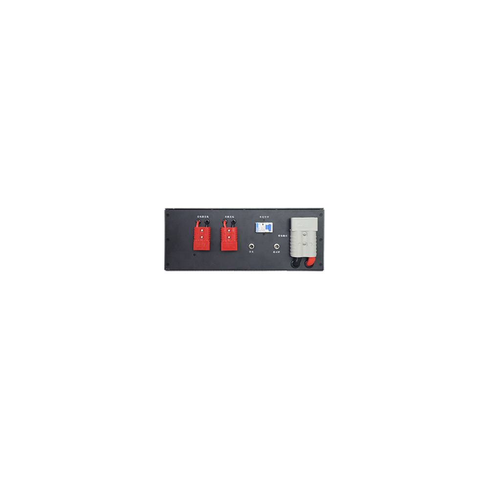
A smart BMS allows the robot controller to use battery data instead of relying only on terminal voltage. Depending on the project, communication can use CAN, RS485, UART or another agreed interface. The protocol must define more than a connector pinout.
- Pack voltage, current and state of charge
- Cell-group voltage and temperature data where required
- Allowable charge and discharge current
- Warning, derating and shutdown states
- Contactor or discharge-output status where applicable
- State of health, cycle count and event history when requested
- Charger-enable and docking-charge information
- Communication timeout and message-validity behavior
The robot-control team should provide the message map, scaling, byte order, update rate, node address and timeout response before BMS software is frozen. A communication timeout should produce an agreed robot response. It should not leave the battery and robot controller making conflicting decisions.
Docking Charge and Opportunity-Charging Design
Docking charge can reduce manual battery handling, but the charging system must be designed around fleet duty. The dock, charger, battery and robot controller need an agreed sequence for contact detection, charging permission, current control and departure.
- Charger maximum voltage and current
- Charging-contact alignment, wipe action and contamination control
- Contact sequence that prevents unintended arcing
- BMS temperature and state-of-charge conditions for charge permission
- Communication or enable line between charger, robot and battery
- Time available at the dock during normal operation
- Balancing strategy and periodic full-charge requirement
- Behavior after an interrupted or incomplete docking event
- Fleet scheduling when several robots share charging stations
Frequent short charging sessions can be practical when the cell, charge current and SOC window are selected for that duty. The project should test the real dock rather than validating only through a laboratory cable charger. Contact resistance, mechanical alignment and software timing can affect charging reliability.
Removable Batteries, Hot Swap and Service Access
A removable robot battery can reduce downtime when charging cannot occur inside the machine. Handles, guide rails, locating features, latches and quick connectors should support safe insertion without transferring pack weight into the electrical contacts.
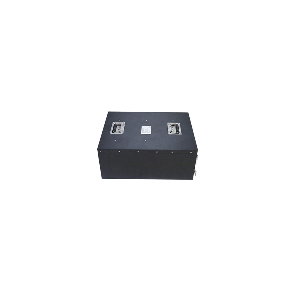
Hot swap is a system function, not a battery option alone. The robot needs a second energy source, controlled bus switching or another method to keep critical electronics powered while the main pack is removed. Connectors and control logic must prevent live contacts from being exposed or connected in the wrong sequence.
Service access should also cover fuse replacement, diagnostic connection, label visibility and pack isolation. If the enclosure must be opened, the procedure should define fastener torque, gasket inspection and any required post-service electrical or ingress test.
Humanoid Robot Battery Packaging and Weight Distribution
A humanoid robot battery affects the robot’s center of mass, balance control and mechanical loads. A pack placed high in the torso can influence stability differently from a lower back-mounted module. Battery mass, location and removal direction should be reviewed with the robot mechanical and controls teams.
- Maximum pack mass and center-of-gravity target
- Available torso, waist or back volume
- Clearance during joint movement and body flex
- Shock loads from walking, running, jumping or falls
- Connector strain during repeated motion
- Cooling path when the battery is surrounded by covers or electronics
- Tool-free or controlled battery removal procedure
- Protection against incorrect insertion or incomplete latching
The enclosure should support the cells throughout the expected motion and shock profile without relying on the connector or outer cosmetic cover. Prototype fit checks should include the complete wiring route, not only the nominal battery volume shown in CAD.
UGV, Inspection Robot and Outdoor Environmental Requirements
A UGV battery or inspection robot battery may face vibration, impact, dust, rain, mud, chemicals and large temperature changes. The required protection should be based on the real installation. A battery inside a sealed robot compartment has different enclosure requirements from an externally mounted pack.
- Vibration spectrum and shock level from the vehicle structure
- Dust, water jets, temporary immersion or wash-down exposure
- Operating and storage temperature
- Low-temperature charging restrictions
- UV, salt fog, oil, fuel or cleaning-agent exposure
- Mounting orientation and drainage around connectors
- Pressure equalization and condensation inside sealed enclosures
Low-temperature cells, insulation or controlled heating can be considered when cold operation is required. Heating energy must be included in the runtime calculation, and charging should remain inside the approved cell-temperature window. For cold-climate projects, see our custom low-temperature lithium battery pack guide.
Thermal Management for Repeated Motor Loads
Robot batteries can experience repeated short power peaks followed by lower-load periods. Average current may appear acceptable even when one cell group, connector or BMS component becomes too hot. Thermal testing should therefore follow the actual mission cycle.
- Measure hot and cold cell locations rather than one average point
- Monitor BMS power components, fuse, busbars and connectors
- Test inside the final robot enclosure with covers installed
- Include charging immediately before or after operation when that matches fleet use
- Check direct sunlight or outdoor enclosure heating where applicable
- Repeat the duty cycle until temperature approaches a stable pattern
Possible thermal strategies include conduction to the battery case, a designed path into the robot structure, forced air outside the pack or project-specific liquid cooling for higher-power systems. The BMS can reduce allowable current at high or low temperature, but derating logic must be coordinated with the robot’s safe-stop behavior.
Custom Robot Battery Specification Framework
| Item | Typical project range or option | How it is confirmed |
|---|---|---|
| Voltage | Commonly 14.4V to 72V, with other platforms reviewed separately | Robot voltage window, charger and subsystem review |
| Capacity and energy | Project-specific Ah and Wh from runtime and duty cycle | Load logging, energy calculation and robot runtime test |
| Chemistry | NMC-based Li-ion or LiFePO4 | Energy density, cycle, current, safety and temperature review |
| Cell format | 18650, 21700, pouch or prismatic where suitable | Packaging, mechanical support and validated cell data |
| Discharge | Continuous and peak current matched to robot loads | Mission-cycle logging and temperature testing |
| BMS | Protection, balancing, SOC and optional event logging | Cell limits, current profile and fault-response plan |
| Communication | CAN, RS485, UART or project-specific interface | Message map and robot-controller integration test |
| Charging | Cable charger, docking contacts or removable-pack charger | Charger specification and complete charge-sequence test |
| Enclosure | Shrink wrap, plastic or metal case with custom mounting | Approved drawing, fit check and environmental test |
| Environment | Indoor, outdoor, low temperature, vibration or ingress target | Application specification and agreed validation plan |
| Documentation | UN 38.3 planning, test summary, SDS/MSDS and project records | Final configuration, destination and applicable standard |
Published ranges are starting points. The production specification is confirmed only after the cell model, BMS, charger, connector, enclosure and validation results are approved together.
Prototype and Robot-Level Validation
Robot battery samples should be tested in the actual platform before pilot production. A pack can pass a bench discharge test and still fail during acceleration, docking, repeated connector use or communication faults.
- Mechanical fit: Confirm dimensions, mounting, insertion, handle clearance, cable route and connector access.
- Power-up behavior: Check inrush current, controller startup and BMS response.
- Mission-cycle test: Run representative travel, turning, lift, joint and compute loads.
- Peak-load test: Measure voltage sag and confirm the BMS does not trip during approved transient loads.
- Runtime test: Record delivered energy and remaining reserve at the end of the real work cycle.
- Thermal mapping: Measure cells, BMS, fuse, connector and enclosure temperatures through repeated cycles.
- Docking-charge test: Check alignment, contact temperature, communication, interruption and restart behavior.
- Communication faults: Test message timeout, sensor faults and the agreed robot response.
- Environmental test: Add vibration, shock, temperature, ingress or corrosion tests where required.
- Pilot fleet test: Compare several batteries and robots to check production consistency.
Acceptance limits should be agreed before testing. Useful records include pack voltage, cell-group voltage, current, state of charge, temperature, fault codes, charge time and mission completion. Our battery quality control process explains how prototype and production checks can be planned.
Fleet Consistency and Pilot Production
For service-robot or inspection-robot fleets, consistency between packs matters as much as the first sample. Cell sourcing, incoming inspection, matching, welding, BMS firmware, calibration, enclosure assembly and end-of-line testing should be controlled under the approved bill of materials.
- Approved cell model and supplier
- Defined cell-matching criteria
- Controlled weld and fastener parameters
- Recorded BMS hardware and firmware version
- Unique pack serial number and traceability
- Charge-discharge and communication test record
- Connector and enclosure inspection
- Reference sample for production comparison
A pilot run can expose assembly variation, cable-routing problems, connector access issues or software differences before a larger fleet order. Changes made after the approved sample should receive documented review because even a small cell, connector or firmware substitution can affect robot behavior.
Certification and Export Documentation Planning
Compliance depends on the final battery configuration, robot type and destination market. UN 38.3 concerns lithium-cell and battery transport testing. It is not a complete robot-product safety certification. Industrial rechargeable batteries may be evaluated against IEC 62619 where applicable, while portable sealed lithium batteries may use IEC 62133-2 depending on the product category.
CE marking is based on the applicable European legislation and conformity assessment for the product placed on the market. It should not be treated as an automatic battery certificate. The finished robot can also have machinery, electrical, EMC, radio or application-specific requirements beyond the battery.
Depending on the approved configuration, documentation support can include the battery specification, drawings, BMS communication information, labels, UN 38.3 test planning and test summary, SDS/MSDS, inspection records and project-specific reports. Certification targets should be agreed before production materials and software are frozen.
Information Needed for a Custom Robot Battery Quote
- Robot type and main function
- Nominal, maximum and minimum operating voltage
- Required runtime or energy target
- Average power and measured mission-cycle current data
- Continuous current, peak current, duration and repetition frequency
- Regenerative current where applicable
- Battery-bay drawing, mounting points and weight limit
- Connector model, cable length and exit direction
- Charger model, docking interface and available charge time
- CAN, RS485 or UART message requirements
- Operating temperature and environmental exposure
- Removable, fixed or hot-swap system requirement
- Applicable vibration, ingress and safety standards
- Destination market and transport route
- Prototype quantity, annual demand and schedule
Battery-bay drawings, connector photos, current logs and charger information provide the best starting point. If the project is replacing an existing robot battery, send the original label, dimensions, connector pinout, communication data and a description of any runtime, charging or shutdown problem.
Related Custom Battery Support
Review our complete custom battery pack engineering service, compare the dedicated 48V LiFePO4 battery design for AGV and AMR platforms, explore other battery application solutions, or send your robot voltage, load profile and battery-bay drawing for an engineering review.
Frequently Asked Questions
Can a custom robot battery be designed for a humanoid robot?
Yes. The design should consider voltage, peak joint and motor current, available torso or back space, weight, center of mass, cooling, connector location and the battery-removal method. Testing inside the complete humanoid platform is recommended before pilot production.
Which chemistry is better for robots, NMC or LiFePO4?
Neither is universally better. NMC-based cells can help when energy density and low pack mass are important. LiFePO4 is often selected when cycle life and industrial durability have higher priority. The decision should include current, temperature, voltage window, space and service-life targets.
Can the robot controller read battery data?
Yes. A smart BMS can communicate through CAN, RS485, UART or another project-specific interface. The message map, update rate, scaling, fault codes and communication-timeout behavior should be agreed with the robot-control team.
Can the battery support docking charge?
Yes. The battery, charger, contacts and robot software should be designed as one charging system. Charge current, contact sequence, temperature limits, communication, alignment and interrupted-charge behavior need validation on the actual dock.
Can a robot battery be removable or hot-swappable?
A removable pack can use handles, guide rails, latches and a quick connector. True hot swap also requires the robot to maintain power and control the DC bus while the main battery is removed. That function must be designed at robot-system level.
How should robot battery peak current be specified?
Provide continuous current, peak current, peak duration and repetition frequency. Include simultaneous drive, lifting, joint and computing loads. Current logs from the actual robot are more useful than a motor nameplate value alone.
Can the battery operate at low temperature?
Low-temperature cells, insulation or controlled heating can be considered. Discharge capability, voltage sag, heating energy and charging temperature limits must be tested at the required conditions. Low-temperature discharge capability does not automatically allow low-temperature charging.
Can a robot battery be waterproof?
Yes, when the enclosure, gasket, connectors, cable exits and pressure behavior are designed for the real exposure. The required IP level and test condition should be defined from rain, water jets, dust or immersion rather than from the enclosure shell alone.
How are robot battery samples tested?
Testing normally includes mechanical fit, startup, peak load, runtime, thermal rise, charging, BMS communication and fault response. Vibration, shock, ingress, low-temperature or corrosion tests are added when required by the robot application.
Which export documents can be supported?
Depending on the final configuration, support can include UN 38.3 test planning and test summary, SDS/MSDS, battery specifications, drawings, labels and inspection records. IEC, CE, CB or robot-level requirements must be confirmed against the final application and destination market.
What information should I send for a quotation?
Send the robot type, voltage window, runtime, average and peak current, battery-space drawing, weight limit, connector, charger, communication protocol, operating environment and quantity. Current logs and battery-bay CAD data can reduce redesign during sampling.